 Click Here for WhatsApp 050 1430209
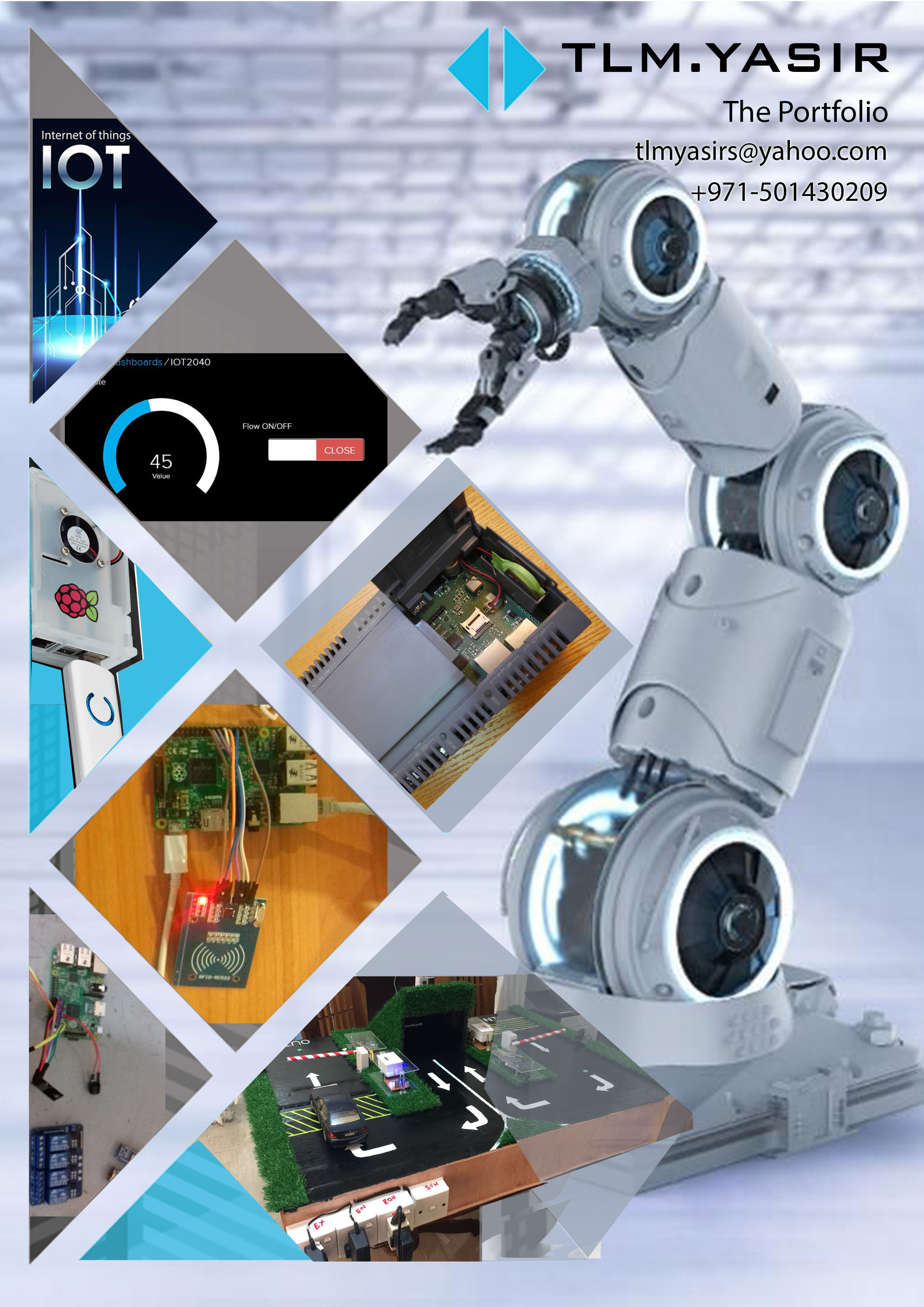
IoT for Home Automation
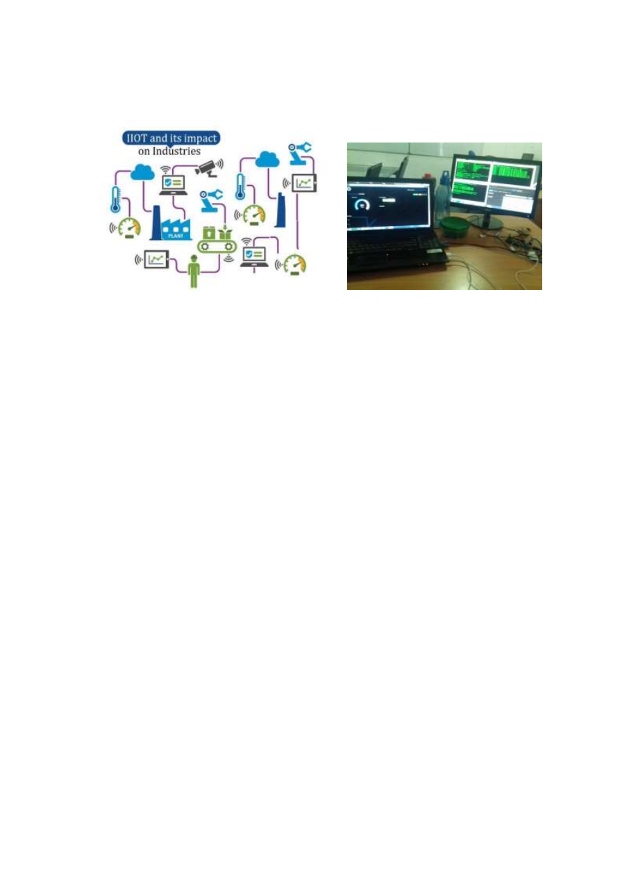
Figure 1 Home automation + IoT photos
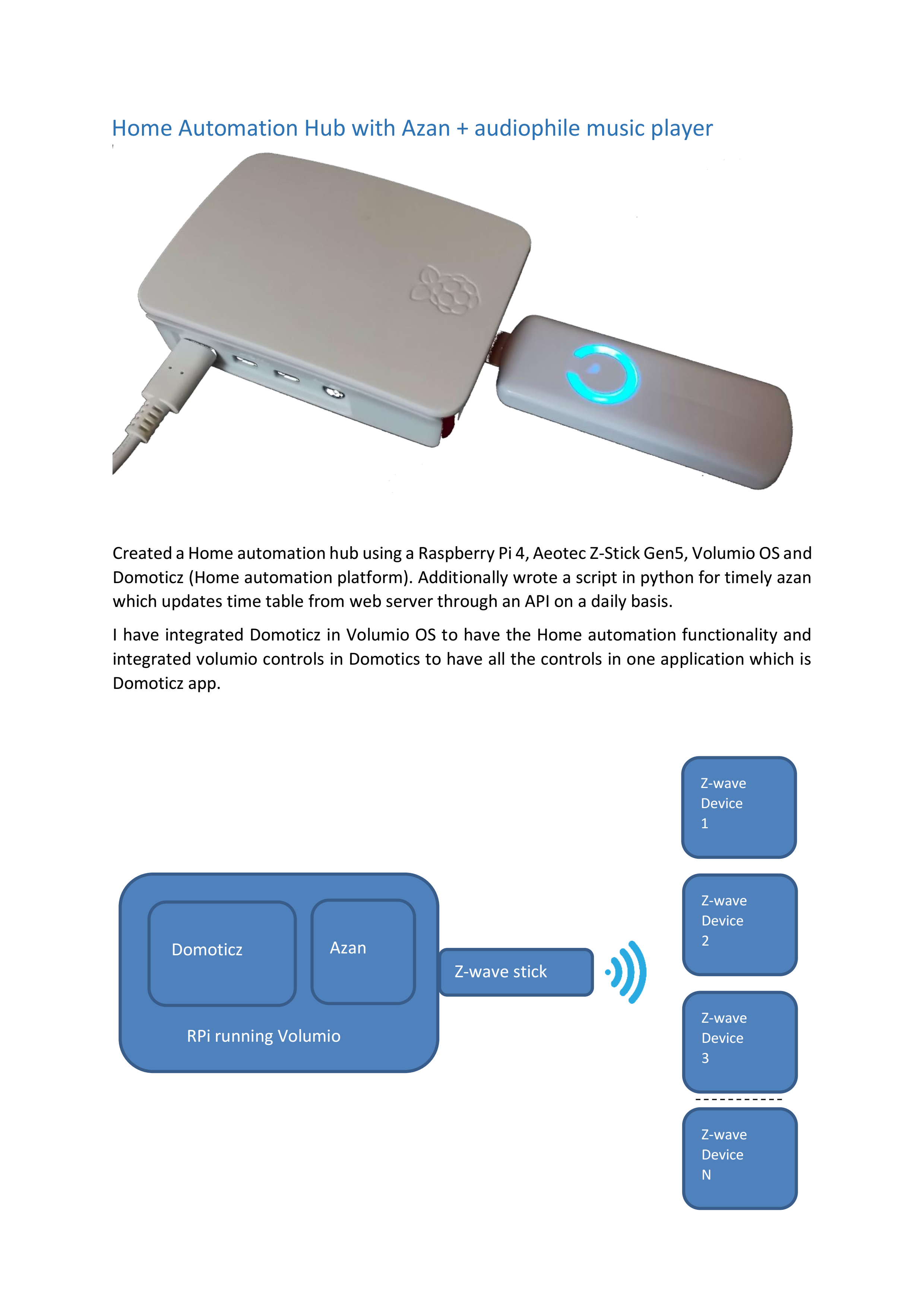
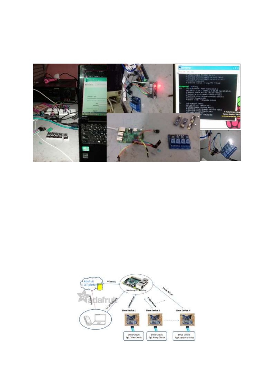
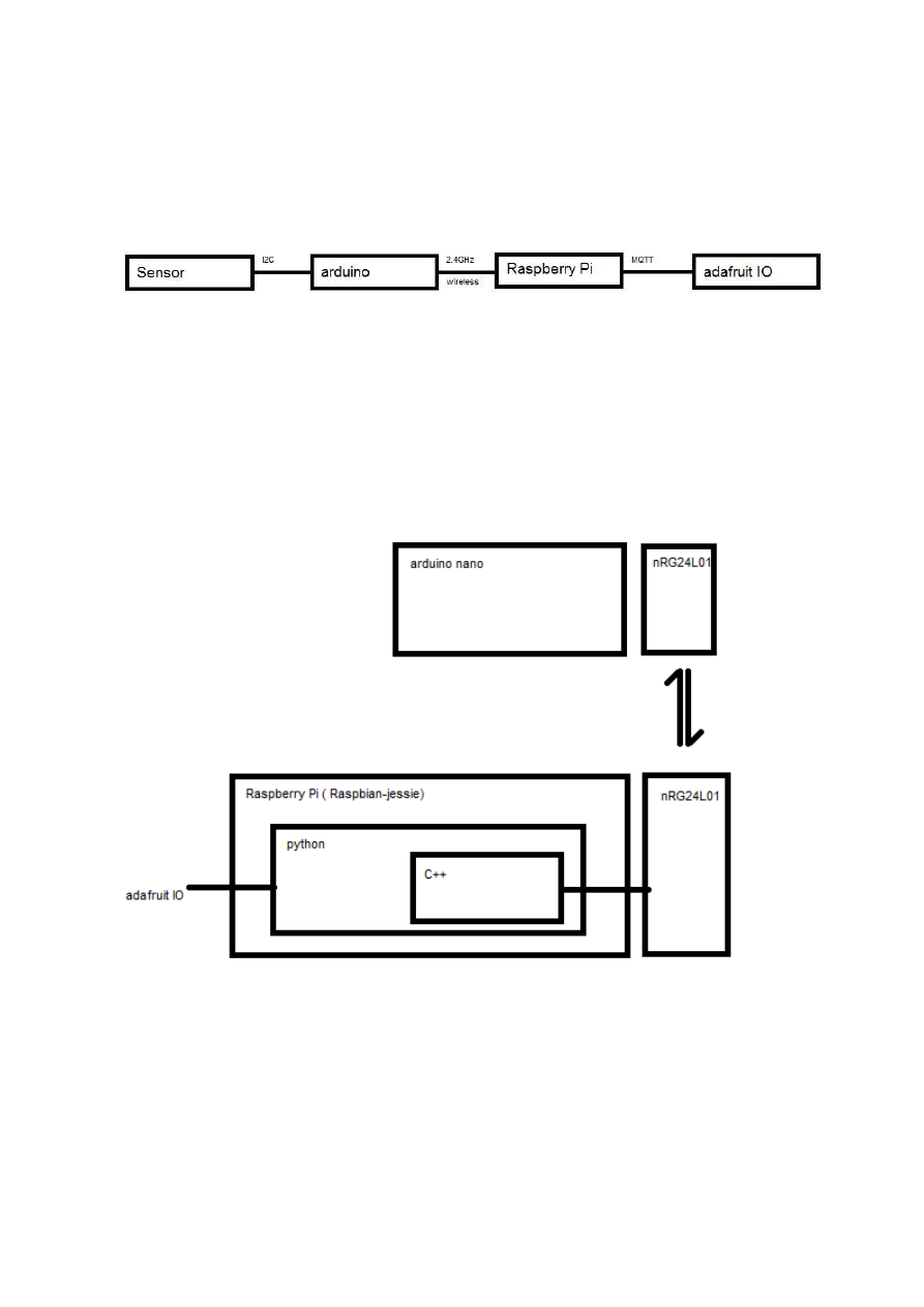
Designed a Home automation system with IoT. The design consists of a Raspberry Pi 2 model B, 4 Arduino nano boards, 5 nRF24L01 wireless modules, sensors, relays, other essential electronic components, and Adafruit IoT platform via io.adafruit.com.
I have used Raspberry Pi’s SPI interface to connect nRF24L01 wireless transceiver module. And sensors and relays connected to Arduino slaves are connected to Raspberry Pi over 2.4GHz wireless communication with the help of nRF24L01.
And this Raspberry Pi is connected to Adafruit IoT platform. So the end devices are online as expressed in the below figure 2.
And Adafruit io has the dashboard to watch real-time and historical data from sensors and control outputs of relay devices. And Adafruit is able to connect to external web applications such as Twitter and IFTTT.
Figure 2 Raspberry Pi Hosting clients to IoT
IoT for Home Automation
Figure 1 Home automation +iot photos
Designed a Home automation system with IoT. The design consist of a Raspberry Pi
2 model B, 4 arduino nano boards,5 nRF24L01 wireless modules, sensors, relays,
other essential electronic components and specially Adafruit IoT platform via
io.adafruit.com.
I have used Raspberry Pi’s SPI interface to connect nRF24L01 wireless transceiver
module. And sensors and relays connected to arduino slaves are connected to
Raspberry pi over 2.4GHz wireless communication with the help of nRF24L01.
And this Raspberry Pi is connected to Adafruit IoT platform. So the end devices are
online as expressed in the below figure 2.
And Adafruit io have the dashboard to watch real time and historical data from
sensors and control outputs of relay devices. And Adafruit is able to connect to
external web application as twitter and IFTTT.
Figure 2 Raspberry Pi Hosting clients to IoT
A machine to machine (M2M) protocol MQTT is used for communication.
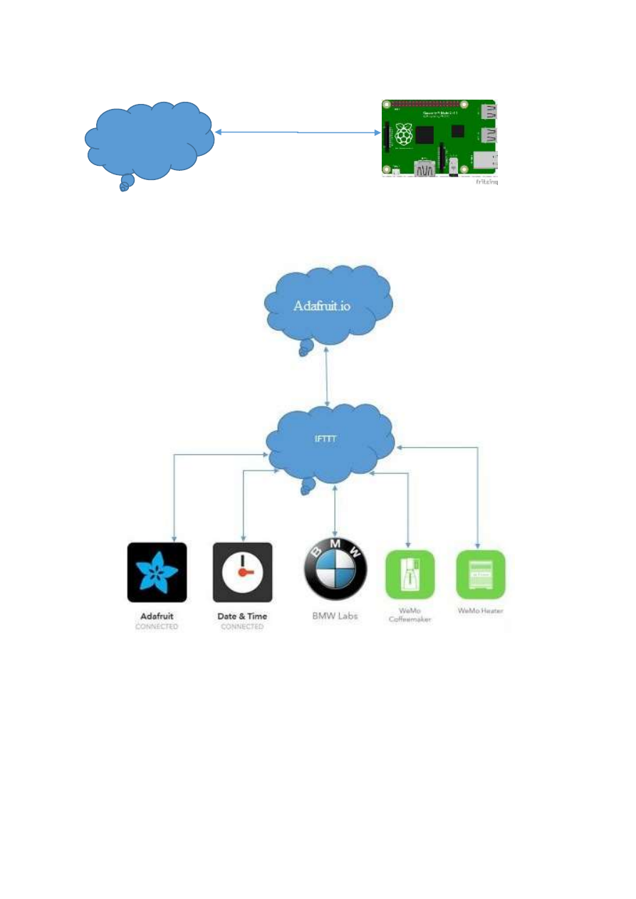
IFTTT
Figure 4 IFTTT
IFTTT is a free web-based service to create chains of simple conditional statements,
called applets. An applet is triggered by changes that occur within other web
services such as Gmail, Facebook, Telegram, Instagram, or Pinterest.
Adafruit IO
MQTT
Figure 3 MQTT
Using MQTT client library I wrote a python code to receive the sensor data and feed
it to IoT platform. I have used a MQTT client application MQTT.fx to do the testing.
The data successfully reached IoT
Figure 5 data flow from sensor to IoT platform
To control the slave I have used C++ to handle wireless module nRF24L01, to feed
the data to Adafruit IO I have used python code. The below figure shows the
architecture.
Figure 6 architecture of relay operation communication
Industrial internet of things (IIoT)
Figure 7 IIOT network example
The application of the IoT to the manufacturing industry is called the IIoT. The IIoT
will revolutionize manufacturing by enabling the acquisition and accessibility of far
greater amounts of data, at far greater speeds, and far more efficiently than before.
A number of innovative companies have started to implement the IIoT by leveraging
intelligent, connected devices in their factories.
Global economy on IIoT
46% of global economy that can benefit from the Industrial Internet
100% Industrial Internet potential impact on energy production
44% Industrial Internet potential impact on global energy consumption[1]
Industry
In order to make better business decisions, the IIoT offers companies the ability to:
Aggregate data from existing sources.
Create additional data sources in a cost effective way.
Gain visibility into new data.
Identify patterns.
Derive insight through analytics.